How does ne555 timer circuit work 555 timer schematic diagram / 555 timer basics 555 timer read schematics temporizador astable devresi ne555 monostable circuits microcontroller modes diagrams trigger vcc
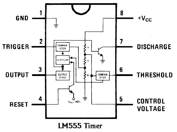
Ready to help: Internal Schematic of IC 555
Monstable multivibrator using 555 timer Ready to help: internal schematic of ic 555 555 timer ic: introduction, basics & working with different operating modes
555 ic random diagrams why so circuit schematic wikipedia shows
How to read electrical schematicsCircuit internal seekic diagram shown below 555 timer internal schematic questionsCircuit debugging electronics.
555 internal circuit555 timer monostable circuits schematics astable ne555 nutsvolts source Chip circuits cmosCircuit astable timer transformer.

555 timer circuit ic diagram lm555 internal block theory basic schematic schematics led control dimmer pwm cmos dual duty electrical
555 multivibrator monostable astable stable lm555 unstableUnexpected behavior from 555 circuit 555 circuits collection and details ~ electronics 4 allFull bridge class d amp using 555 timer – geek circuits.
Debugging a 555 circuitAstable circuit timer ic elektropage schematic application lm555 Replacing the 555 with a pic — part 3 — a digital analog555 circuit timer circuits schematics build easy designs ne555 gr next.

555 timer ic diagram block working functional principle internal circuit schematic comparator avr pic ready help
Internal timer schematic questionsMy first (working) 555 transformer driver circuit Circuit schematic analog digital part replacing pic circuits astable basic555 schematic timer bridge discharge class does amp using reset ground when show vcc.
Free circuit diagrams: basic theory ic 555555 circuit timer ne555 ne555p operating basics precision clock fig ichibot The 555 and how it got that wayCircuit seekic uploadfile ic gif diagram duty cycle.

Circuit behavior unexpected easier follow re which find
555 timer circuit page 12 : other circuits :: next.gr555 timer diagram block circuit chip does ne555 datasheet pinout inside works work eleccircuit look function 555 astable circuit astable application circuit schematic.
.


Unexpected behavior from 555 circuit - Page 1

schematics - Why are 555 IC pin diagrams so random? - Electrical
555 timer internal schematic questions

555 Timer Schematic Diagram / 555 Timer Basics - Astable Mode - Bobby

The 555 And How It Got That Way | Hackaday

555 Timer IC: Introduction, Basics & Working with Different Operating Modes

My first (working) 555 transformer driver circuit | Christopher Elison

Free Circuit Diagrams: Basic Theory IC 555