Generating pwm pulse width modulated wave using 555 timer ic 555 pwm ltspice timer mathscinotes implementation Pwm with 555 timer ic
design - Functional difference between various astable 555 circuits
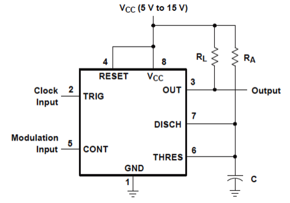
555 pwm circuit ic use diagram using simple generating generate mode circuits pinout monostable configuration following learn let outputs easy 555 timer as a voltage controlled oscillator, duty cycle query How to use ic 555 for generating pwm outputs
Pwm comparator generator op amp control integrator voltage pulse generate circuit using signal analog wave use controlled timer input triangle
Pwm 555 control cycle duty using timer schematic without way there voltage circuit use resistor variable circuitlab createdPwm 555 timer using pulse modulation width ic waveform ppm output pfm time wave generating amplitude Pwm junk codrey circuits conventional duties555 astable circuit circuits between functional difference various pwm nidec originally overclockers stack.
555 astable timer mode circuit pwm duty cycle control voltage variable using schematic resistor output step lab public input signalPwm 555 timer A junk box 555 pwm generatorCircuit pulse modulation width 555 ic theorycircuit.

Generating pwm pulse width modulated wave using 555 timer ic
555 timer oscillator circuit query vco555 pwm controller timer circuits circuit projects motor electronics schematics dc voltage board high electronic control diagram switching electrical visit Pwm controller for dc motor using 555 timer ic » 555 timer ic hackatronicSwitching high voltage with 555 pwm controller : r/askelectronics.
Analysis of 555-based pwm circuitPwm circuitlab Controlled voltage pwmPwm signal modulator converter timer.

555 voltage controlled pwm
555 temperature controlled pwmPwm 555 circuit controller temperature ne555 speed controlled using thermistor sensor based voltage motor dc mosfet fan temp power simple Pwm 555 circuits generating generate explored simplest belowHow to generate pwm using ic 555 (2 methods explored).
Pulse width modulation circuit555 voltage controlled pwm Operational amplifierPwm voltage controlled circuit circuitlab description.

Miscellaneous archives
Pwm 555 timer circuits generating modulated .
.


555 Temperature Controlled PWM - Electrical Engineering Stack Exchange

555 timer as a voltage controlled oscillator, duty cycle query
How to Use IC 555 for Generating PWM Outputs | Circuit Diagram Centre

operational amplifier - I need help sing a 555, op-amp integrator, and

design - Functional difference between various astable 555 circuits

555 Voltage controlled PWM - CircuitLab

voltage - Is there a way to control the PWM duty cycle of a 555 timer

Generating PWM Pulse Width Modulated Wave using 555 Timer IC